
NACA 0012 airfoil lift study
I used MATLAB to model a NACA 0012 airfoil with a vortex panel method, discretizing the boundary into panels and control points. The analysis examined pressure coefficient distributions and the change in lift coefficient as angle of attack varied from −5° to 12°.


The fitted numerical slope was approximately 10.8% above the thin-airfoil reference. The comparison provided a check on the implementation and its discretization. The model assumes inviscid, incompressible potential flow; the lift sweep does not predict viscous separation or stall.
Heat conduction around two water passages
I modeled the temperature field in a 1.0 × 0.6 m commercial-bronze cross section containing two 0.2 × 0.2 m square water passages. The setup applies heat flux at the top surface and uses the internal passages to remove heat.

The MATLAB setup uses a 101 × 61 grid, thermal conductivity of 52 W/(m·K), a convection coefficient of 500 W/(m²·K), a water temperature of 50 °C, and an applied radiation heat flux of 1,200 W/m².
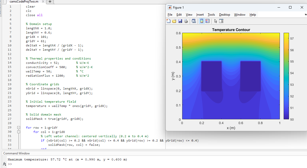
The contour plot shows the cooler regions around the passages and the rise toward the heated upper surface. This is a numerical result from the modeled boundary conditions.