Turning drawings into working hardware
I manufactured engine components and assembled the Stirling engine into a working mechanism. I wrote the tooling and manufacturing documents, selected tools, and determined machining speeds for the materials and operations using machining equations and process rules.
The documentation covers components including the piston wheel, piston and flywheel supports, piston housing, base, displacer components, and flywheel. It connects dimensions and fit requirements to machining setups and assembly.
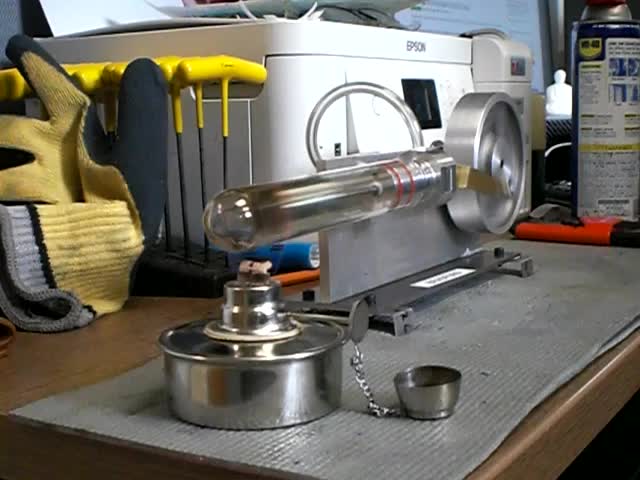
The assembled engine in operation
Process plans and tool selection
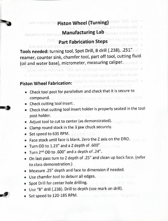
I authored the tooling documents and worked out the machining parameters rather than simply following a supplied tool list. I used cutting-speed equations and material- and process-specific rules to determine spindle speeds, then documented the tools, setups, and operation sequence.
I related cutting speed, tool or workpiece diameter, and spindle RPM, then applied the appropriate rules for the material and operation. The plans translate those choices into practical steps for the mill and lathe.
The manufacturing packet pairs part drawings with sequences for turning, milling, drilling, reaming, tapping, and deburring. Tool lists include turning tools, spot drills, drill bits, reamers, end mills, edge finders, taps, and inspection tools.
The plans address workholding, finding and zeroing part locations, machining order, and dimensional checks. Examples below show the piston-wheel drawing and the turning and milling instructions used to translate it into a finished component.