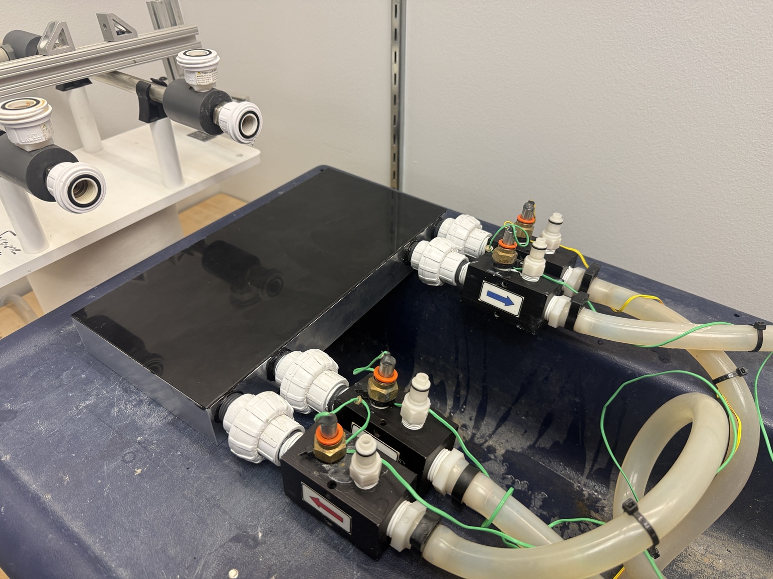
Two water circuits inside one aluminum billet
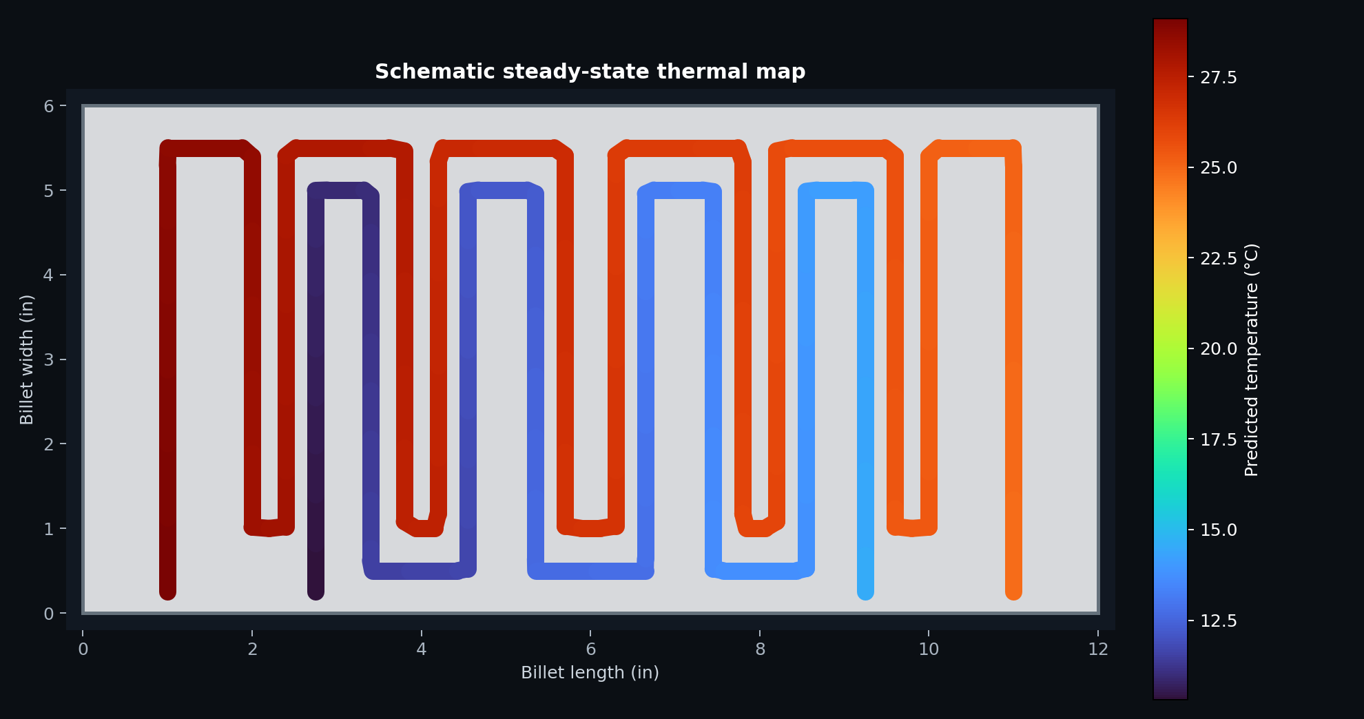
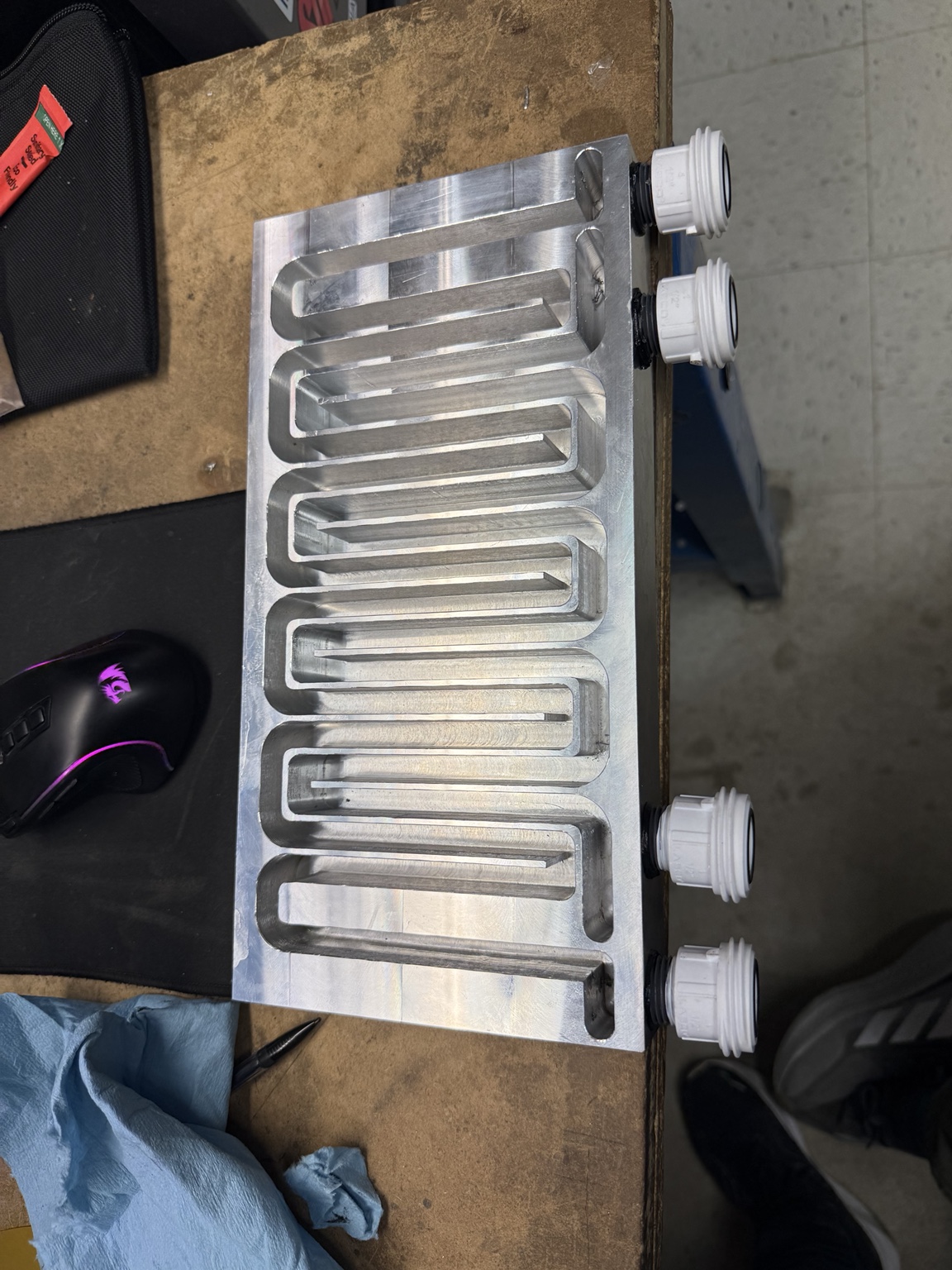
The design packages separate hot- and cold-water serpentine paths into a 12 × 6 × 1.5 inch aluminum body. A longer outer hot channel surrounds a shorter cold channel, creating repeated adjacent runs separated by a 0.100 inch aluminum wall. Four ports allow the same hardware to be configured for parallel or counterflow operation.
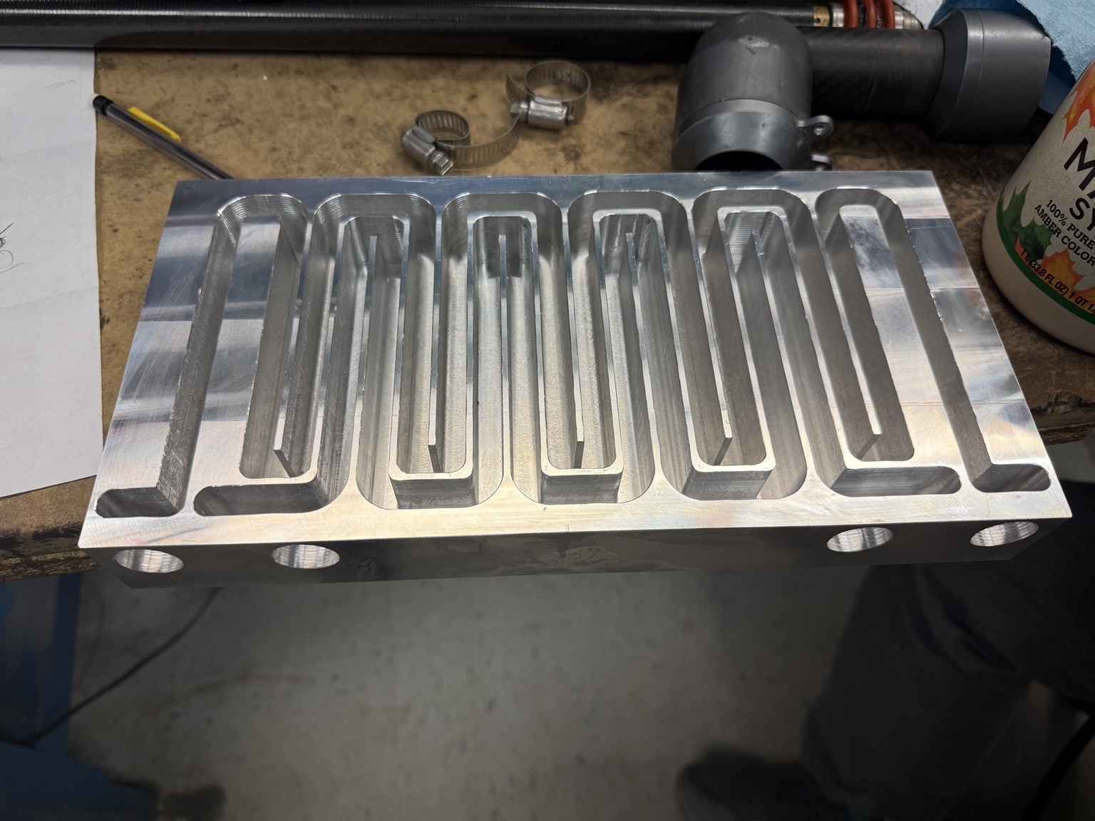
The channels were modeled from their CAD plan-view areas rather than treated as generic tubes. That geometry established centerline lengths of 1.615 m on the hot side and 1.101 m on the cold side, with an effective shared-wall area of 0.0699 m² after accounting for both sides of the inner channel.
Connecting geometry, flow, heat transfer, and pressure loss
I created and ran a MATLAB model that links the physical channel geometry to thermal and hydraulic performance. It calculates water properties, rectangular-channel hydraulic diameter, Reynolds and Nusselt numbers, convection coefficients, aluminum-wall resistance, overall conductance, NTU-effectiveness, outlet temperatures, LMTD, heat duty, and Darcy-Weisbach pressure drop.
This is a calibrated first-pass engineering model, not CFD. It assumes steady state, liquid water with constant properties, an externally adiabatic body, one-dimensional wall conduction, fully developed flow, and zero contact resistance. Serpentine mixing is represented with a conservative Nusselt enhancement factor.
Baseline model output
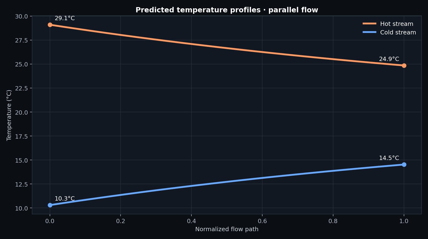
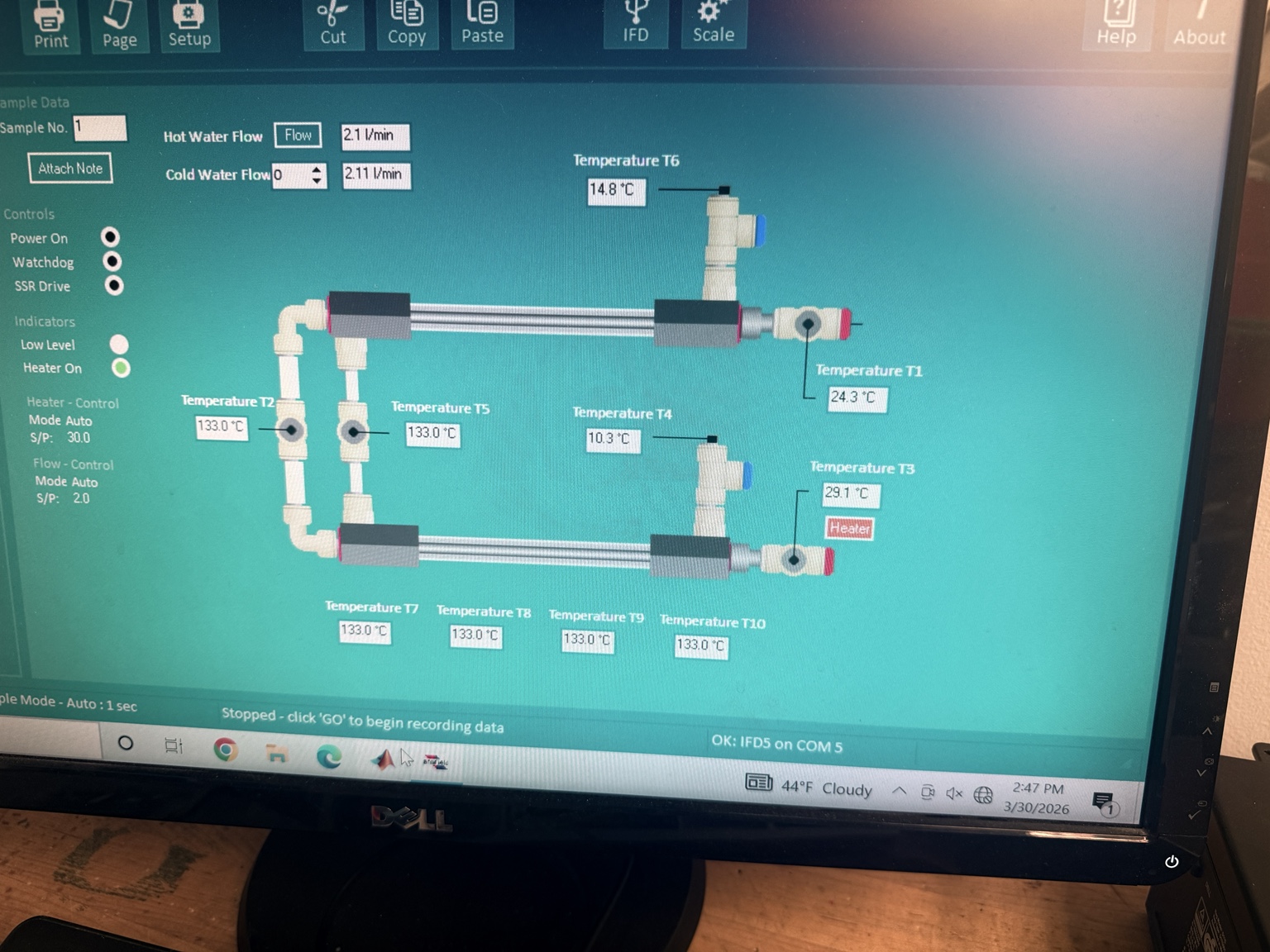
The baseline parallel-flow run used 2.10 L/min hot water, 2.11 L/min cold water, a 29.1 °C hot inlet, and a 10.3 °C cold inlet. It predicted 620.7 W of heat transfer.
Machining the thermal architecture into hardware
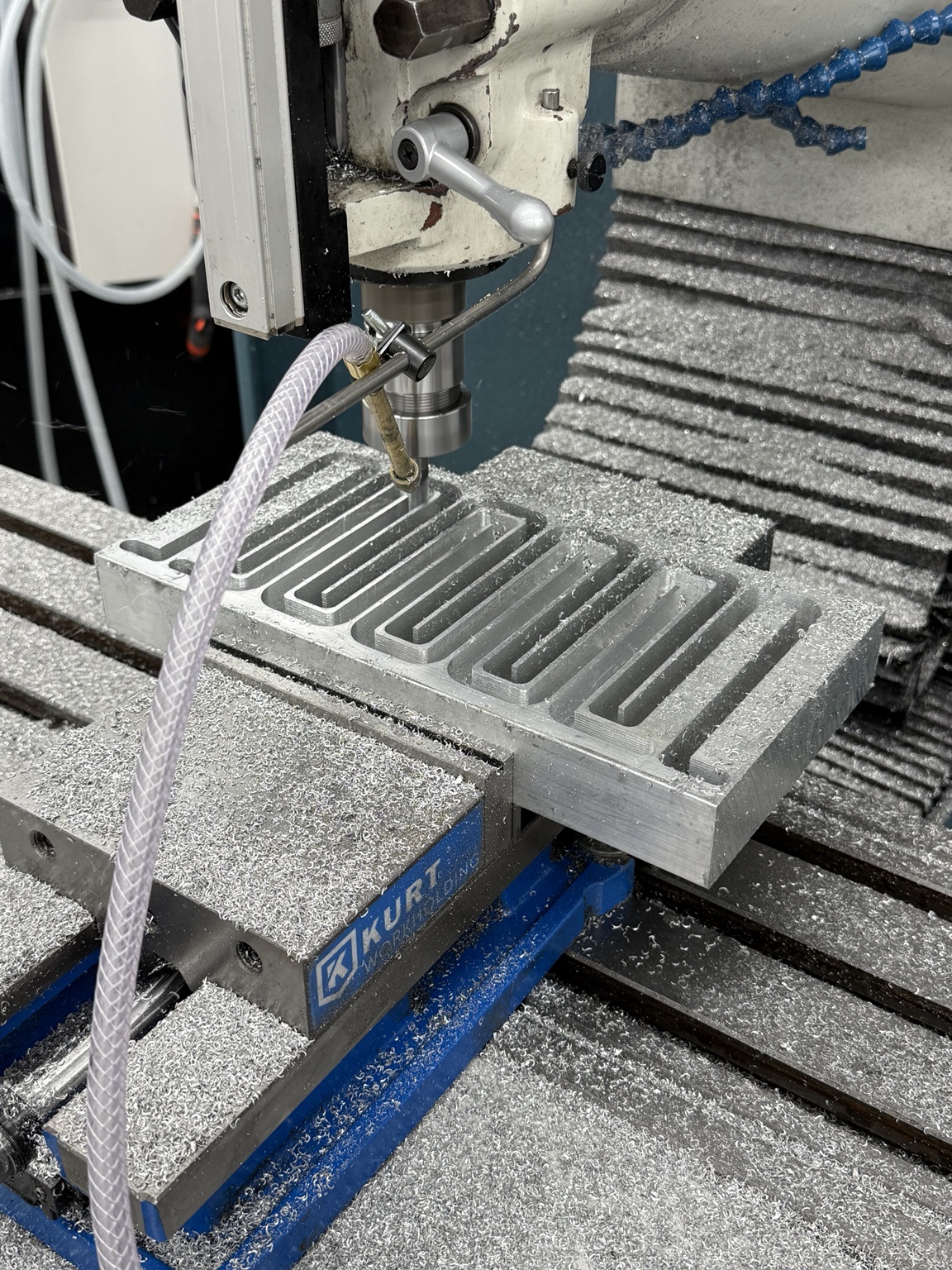
The serpentine paths, port interfaces, and sealing surfaces were translated into machinable geometry and cut from the aluminum billet. I helped manufacture the billet on the CNC mill, turning the modeled channel network into the physical hot- and cold-water paths. The finished body received four threaded connections, a thin cover plate, and an adhesive sealing system before being integrated with fittings, hoses, thermocouples, and pressure taps.
Testing showed strong heat transfer and energy balance
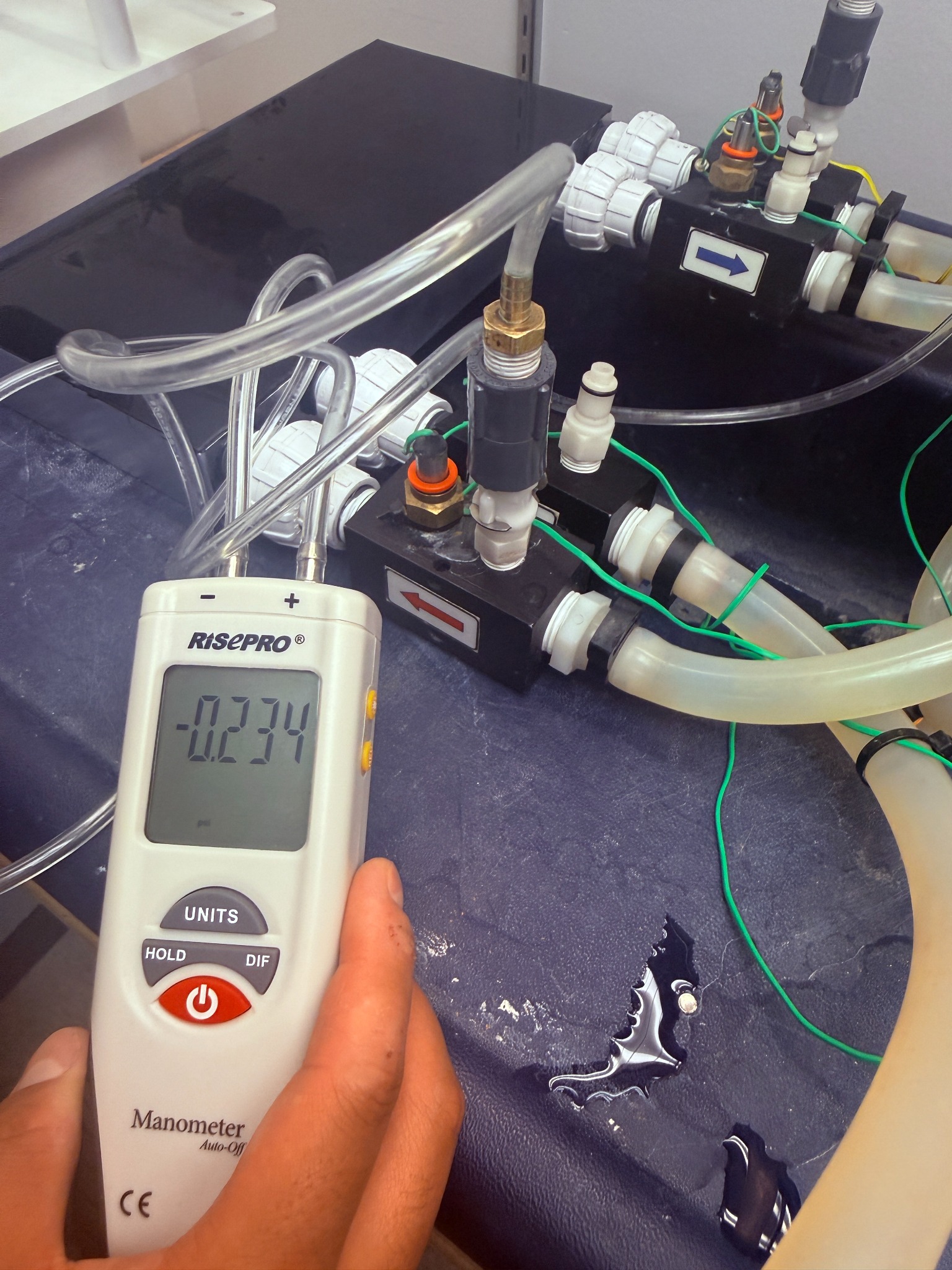
The completed exchanger was tested in parallel flow with the hot stream routed through the longer channel. The instrumented loop recorded both flow rates and all four inlet/outlet temperatures, while a manometer measured the pressure change through each side.
*Cold-side pressure is shown as magnitude; the recorded manometer value was −0.53 kPa because of the measurement orientation.
Compact performance with clear next-generation priorities
Against the laboratory’s commercial tubular exchanger, the custom billet produced more heat transfer and substantially stronger volume- and pressure-normalized figures of merit. The commercial unit remained better on a mass basis because it was significantly lighter.
The 0.95 energy balance indicates modest heat loss and measurement uncertainty. The low-NTU result identifies heat-transfer area—not simply flow rate—as the main development constraint. A next iteration would increase area through additional or multilayer channels, improve flow uniformity, reduce adhesive/contact resistance, and add insulation around the body.
From equations to an operating thermal system
My work centered on the mechanical and analytical core: translating channel geometry into a thermal/hydraulic model, implementing and running the MATLAB simulation, interpreting U/NTU/effectiveness and pressure-loss behavior, helping machine the aluminum billet on the CNC mill, and carrying the design through assembly, instrumentation, and operation.